
A print arrives with “32” next to one face of a manifold. The supplier needs to know whether this refers to roughness, which unit applies and whether the value is a limit. The mark may control the finish of a sealing face while the rest of the block can keep its normal machined texture. Clarifying that distinction changes both the process plan and the inspection quote.
Read the parameter and the units together
Ra is the arithmetic mean of the absolute deviations of a measured roughness profile from its mean line. It describes the surface along the measured trace. Rz is a different parameter based on peak and valley heights. A narrow scratch and a broad shallow pattern can affect the two values differently. There is no universal factor that converts Ra into Rz. Confirm the specification and parameter before using a chart.
One microinch equals 0.0254 micrometres. The table converts the same Ra value between units. The last column shows a common rounded reference for discussion. Use the drawing's stated value and units for acceptance, particularly when two rounded numbers would set different limits.
| Ra (µin) | Exact conversion to Ra (µm) | Rounded reference (µm) |
|---|---|---|
| 125 | 3.175 | 3.2 |
| 63 | 1.6002 | 1.6 |
| 32 | 0.8128 | 0.8 |
| 16 | 0.4064 | 0.4 |
| 8 | 0.2032 | 0.2 |
Tell the shop which face matters
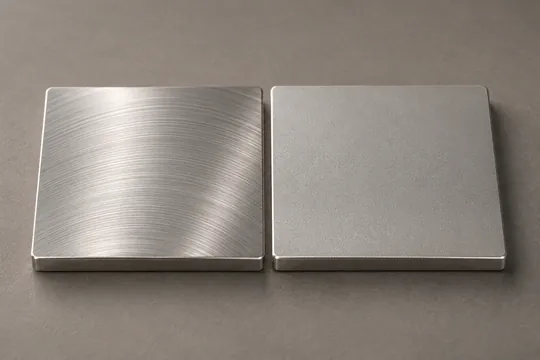
Mark the controlled face on the 2D drawing, and state when it is inspected. A bore that receives a coating may need a requirement on the finished surface. A masked mating face may have its controlling measurement on the machined surface instead. For a cosmetic cover, agree a finish sample and viewing conditions if appearance matters. Two faces can share an Ra value while different tool patterns make them look different.
When fluid retention, sealing or sliding contact matters, the texture direction can be as important as its average height. State any functional lay requirement, and ask the design engineer whether another parameter or a separate scratch criterion is needed. Put a finish requirement on the affected face to avoid adding inspection work to unrelated surfaces.
Agree how the surface will be measured
Reference the applicable drawing standard and edition. Where the part or customer specification requires it, record the filter setting, evaluation length, trace direction and measurement locations. Give particular attention to narrow lands or recessed surfaces, where the stylus might lack room to complete the intended trace. Agree a suitable method before the order is placed and record any approved departure from the original requirement.
Example quote request
“On face A, quote a maximum Ra of 0.8 µm after the final machining operation. Face A is identified on the attached drawing. The cover will be coated elsewhere; mask face A. Please confirm the proposed measurement locations and whether a roughness result can be supplied for the first article.” Provide the real inspection requirement and reference drawing with the request so engineering and purchasing evaluate the same scope.
Can a surface meet Ra and still have a visible scratch?
A machining surface finish chart helps interpret the roughness value. A local scratch on a visible cover is a separate acceptance question, even if a roughness trace taken elsewhere meets the drawing.
Mark the appearance zone and give a separate scratch criterion or approved visual reference. Record the roughness measurement location so the numerical result and the visual decision can be reviewed independently.


 English
 German
 Spanish
 French
 Russian
 Japanese