コンテンツへスキップ
| 目次 |
| Introduction to Composite 3D Printing |
| Composite Materials for 3D Printing |
| Suitable 3D Printers |
| Print Setup and Slicing for Composite Materials |
| Post-Processing of Composite 3D Prints |
| Example Composite Parts and Applications |
| Advanced Techniques in Composite 3D Printing |
| Post-Processing for Enhanced Performance |
| Material Testing and Certification |
| Future of Composite 3D Printing |
| 結論 |
| よくある質問 |
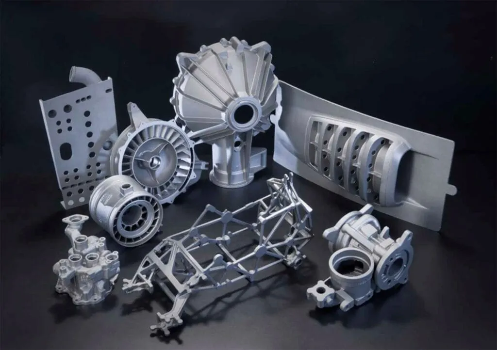
3Dプリンティング with composite material is a more sophisticated idea other than the general 3D printing with plastics such as PLA or ABS. Materials like carbon fiber, fiberglass and continuous fiber reinforcement can be incorporated with the 3D prints and the resulting products will be much stronger and lighter as well. Carbon fiber filament and continuous carbon fiber or fiberglass strands woven into a filament or deposited layer by layer translate into 3D printed parts to resist forces than conventional plastics. In this guide, you will learn what actually constitutes composite 3D printing and how to begin this process. It will include topics such as suitable CFF material, suggested 3D printers, proper method of preparing prints, and examples of the various printed composites for aplikasi. Understanding the methods outlined in this guide means mastering how to make reliable end-use parts using high-performance composites.
Composite Materials for 3Dプリンティング
Fiber-Reinforced Filaments
Short fibers are used in filaments to reinforce different parts of a 3D printed plastic. Two there are those such as the carbon fibre filament and the fiberglass filament. Carbon fiber filament consists of short carbon fibers of ¼ inches length are embedded in a plastic polymer. The carbon fiber augments the strength and enhances rigidity of prints in our experiments. However, short fiber length indicates that it will not be as strong as continuous fiber in prints. It is also considerably more susceptible to breakage than fiberglass. However, carbon fiber permits the creation of comparatively very strong but relatively lightweight components good for uses in such applications as the housing, enclosure and others requiring strength and sturdiness. Fiberglass filament uses short strands of fiberglass and not carbon.It produces strong prints that are dense, heat-resistant and less brittle than carbon fiber. Fiberglass prints are well-suited forsnap-fitting parts, enclosures and prototyping tools. A downside is strength gains over plain plastic are not as great as with carbon fiber.
Continuous Fiber Reinforcement
Carbon Fiber Tow/Tape
Continuous fiber reinforcement uses long, unbroken carbon fiber strands laid directly into 3D prints layer by layer. Common continuous fibers are carbon fiber tow or tape. Tow refers to many filaments bundled together while tape has individual filaments held together.
The carbon fibers are embedded in a matrix material like ABS or PLA which is then 3D printed. Using uninterrupted carbon fibers leads to incredibly strong prints that act almost like carbon fiber composites. Extended fibers align strength in strategic load bearing directions. Parts can withstand high impact, tension and bending forces.
アプリケーション
- Carbon fiber is well-suited for structural or load-bearing applications where lightweight strength is important like drones, robots, housings.
- Fiberglass works well for enclosures, housings and snap-fit parts needing durability and heat-resistance.
- Tow/tape give high performance benefits and are suitable for functional prototypes, production molds and aerospace components.
Suitable 3D Printers
Fused Filament Fabrication (FFF/FDM)
FFF/FDM printers like the Prusa MK3s, Ultimaker S5 and MakerBot Method are well-suited for composite filaments and layup printing with continuous fibers. In FFF, composite filament is extruded to fuse layers together across the print. Individual carbon fibers are randomly oriented but bulk strength improves. The low viscosity of molten plastic wets-out continuous fibers for good bonding layer to layer following the head movement.
Beginners can start with low-cost printers like the Ender 3, while serious users choose larger builds like the Lulzbot TAZ or custom modded machines. All-in-one options like the Mark Forged Mark Two integrate continuous fiber laying.
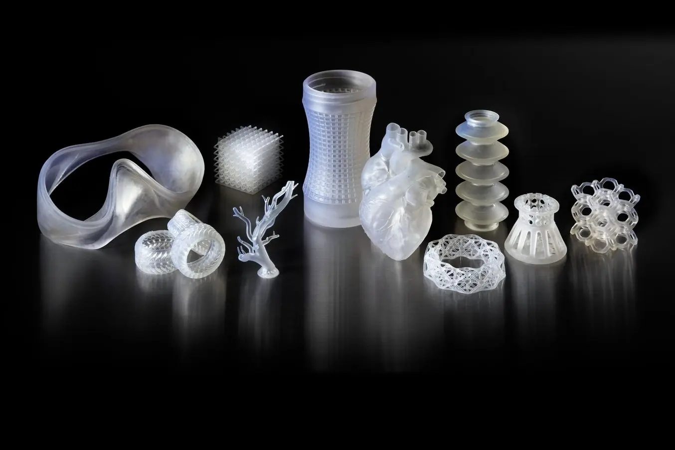
Stereolithography (SLA) & Digital Light Processing (DLP)
エスエルエー and DLP printers offer resolution benefits for composites. The Formlabs Form 3 prints nested continuous fiber meshes with high precision. Resins containing suspended ceramic or graphene particles produce very strong, heat-resistant parts. Curing happens rapidly layer-by-layer so fibers don’t move during printing. However, support structures may damage fibers requiring extra post-processing.
選択的レーザー焼結(SLS)
SLS can 3D print non-reinforced nylon and composite powders laid through coaxial feeders. The EOS P 395 for example infuses long carbon fibers during printing. Parts exhibit high creep resistance and withstand forces in any orientation. However, the technology carries a higher price point.
Print Setup and Slicing

Slicer Settings
When setting up slicer profiles for composites, go slower than typical prints. Reduced speeds around 30mm/s give fibers time to properly embed. Heat should also be fine-tuned to fully melt fill material around fibers. Additional interface layers help bonding.
Support settings require optimization to minimize fiber contact. Rafts can often substitute supports under large areas. Brims add adhesion without touching the print.
Tools and Loading
Carbon fiber tows require cutting before use. Scissors work but a razor works best. Use tweezers to carefully insert into the feeder.
For layup printers, load the continuous fiber spool and matrix filament separately to control flow. Calibrate until they join precisely at the tip.
Calibration
Test a basic 3D shape at low speed with varied extrusion widths and overlaps. Inspect for voids, kinks and strength to identify optimal settings.
Bed Adhesion
A raft layer is recommended for carbon fiber prints. Glue or tape may be needed to prevent delamination of the first layers. Brims add grip without touching the main print.
後処理
Support Removal
For SLA/DLP prints, dissolve supports in water for quick removal without damaging parts. Or vapor polish with acetone to smooth surfaces.
仕上げ
Sand composites starting at 150-grit, moving up through grits to 400 or 600. This buffs layers and fills gaps.
Apply filler primer or bondo to fill remaining pores. Sand again when dry.
Primers promote paint adhesion and help achieve a glossy finish. Use primers suited for plastics.
Sealing
Apply 2-3 thin coats of polyurethane sealant with a brush. This strengthens and protects prints while maintaining a paintable surface.
絵画
Spray or brush on auto paints for a high quality painted finish. 2K (two part) paints offer show-quality results.
Clear Coat
Apply 2-3 thin coats of clear polyurethane to seal and protect the color coat. Buff as desired.
Avoid: processes producing fumes like acetone or chemicals that could damage fibers such as paint thinners.
Example Composite Parts
Motorsports
Carbon Fiber Spoiler
A rear spoiler was printed flat in carbon fiber filament then heat formed using a mold. Printing laid down fibers parallel to airflow. Hot water gently formed the shape.
Fiberglass Brake Ducts
Directing air to brakes, these ducts were first printed as a mold in PLA. It was then coated to seal. Fiberglass resin and mats were laid in and cured.
ロボット工学
Reinforced Drone Arms
Arms were printed in two pieces using carbon fiber. Joints were epoxied. Carbon tape strengthened joins while TPU printed bushes aided articulation.
Carbon Fiber Grippers
Grippers to pick objects require strength and precise sizing. Cast nylon jaws and PLA housings were fiber reinforced. Carbon fiber tow insertion built them tough.
Manufacturing
Fiberglass Prototype Enclosure
An enclosure’s mold was 3D laid up from ABS and fiberglass continuous tow on the Mark 2 at 0.5mm layers. It withstands sanding and prototyping.
Composite Injection Mold
Using hi-temp ABS and HexTow on the Fortus 450mc, this brake manifold’s mold channels cooling and tolerates injection temperatures.
消費者
Carbon Fiber Phone Case
Using the P3 Metal to embed unidirectional prepreg to aligned layers, this case protects from impacts and precisely fits various phone models.
Fiberglass Frames
Eyewear frames were printed in ABS with fiberglass for comfort, flexibility and impact resistance. Thin walls were reinforced throughout.
Art/Design
Continuous Fiber Sculptures
Complex shapes like twisting coral were replicated in nylon with long carbon fibers following contours for strength without compromising aesthetics.
Fiber Reinforced 3D Prints
Art pieces are strengthened using chopped fiberglass in ASA printed on a Markforged printer without compromising detail resolution through their continuous fiber infused prints.
Advanced Techniques
Layup Printing
Layup 3D printing allows precise unidirectional or woven fiber placement. The Markforged Mark Two prints ABS while continuously laying down carbon fiber spools or rolls of fabric like twill weave. Each layer precisely places reinforcements using vision guidance. Complex geometries like lattice structures can be reinforced minimally.
Multimaterial Multiextrusion
Some printers like the Formlabs Form 3 can print multiple materials simultaneously through independent extruders. Nylon parts with selective surfaces of exposed continuous carbon fiber or Kevlar could be produced. Different visual properties reinforce strategic high-stress directions.
Modeled Reinforcements
In CAD programs like Fusion 360, reinforcement paths can be drawn into designs to be directly sensed and followed by the printer. Internal lattices effectively strengthen parts where needed without adding excess material. Slicers now detect these paths for optimal reinforcement.
Composite Prototyping Projects
A drone airframe was layup printed at 0.1mm from ABS and unidirectional carbon fiber. Internal channels were printed. Sensors were cast directly in.
A high-end scooter was prototyped. Frame parts were printed in continuous fiber nylon. Internal wiring and controllers were added to demonstrate integrations.
Embedded Electronics
Sensors, batteries and simple circuits can be molded into composite parts during 3D printing by placing components inside open cavities, then printing a sealed top layer. Reinforcements secure connections. Openings may be added for programming access.
Post-Processing for Performance
Infill Optimization
Honeycomb and triangle infills maximize strength for low densities below 30%. Rectilinear is best above 40% density. Lines aligned along load paths improve strength-to-weight ratios of composite parts.
Thermal Curing
For parts made of resins, additional heat curing helps fully crosslink polymers for maximum properties. A convection oven at 80C for 2 hours post-print is common.
Machining
Standard CNC machining perfects 3D printed composites. Milling pockets and slots complements 3D printing for moving fittings, ports or other fixtures. Drilling mounting holes finishes prototypes.
Bonding
For bonding or repair, use epoxies formulated for composites. Surface preparation improves adhesion. Clamp while curing. Custom adhesives can join multi-material prints.
Surface Treatments
Sanding with high grits creates a smooth surface. Primers promote paint adhesion and corrosion resistance. Chemical passivation protects metal parts. Anodizing increases hardness, wear resistance and coloring options for aluminum.
組み立て
After machining, parts can be bolted, snap-fitted or ultrasonically welded together. Fastening tabs reinforce joins while simplifying construction.
Material Testing and Certification
Mechanical Testing
Tensile, flexural and izod/charpy impact tests determine a material’s strength, stiffness and toughness. ASTM standards like D638, D790 and D256 specify test methods.
3D Printing Standards
Additive manufacturing processes require consideration of layer interfaces and anisotropy. ASTM F2971 covers guidelines for testing 3D printed thermoplastics.
Documentation
Maintain a project workbook fully detailing materials, print settings, post-processing and test procedures. Record all metrics.
認証
For regulated industries, parts may need ISO or FDA approval. Underwriters Laboratories certification demonstrates safety. Data substantiates compliance.
Non-Destructive Testing
Ultrasonic C-scan detects internal defects. X-ray radiography images flaws. Dye penetrants highlight surface cracks. This quality control ensures integrity.
Importance of Testing
Certified data is necessary to prove aerial, medical or otherwise critical parts can withstand real-world forces. Testing preserves liability for composite printed components. Repeated validation ensures consistent, reliable quality.
結論
In conclusion, this guide has provided an overview of advanced 3D printing techniques using composite materials. Key learning points include suitable materials like carbon fiber and fiberglass filaments as well as continuous fiber reinforcement. Recommendations of FFF/SLA/SLS printers, optimized slicing profiles, and post-processing steps like machining were covered. Example composite printed parts demonstrated applications in motorsports, robotics, manufacturing and more. Advanced methods such as layup printing, embedded electronics integration and performance-focused techniques like heat curing extend composites creativity. The strength and customizability of 3D printed composite parts makes them ideal for functional prototypes and production applications. As both materials and processes continue improving, composite 3D printing promises an increasingly bright future in manufacturing. Readers are encouraged to pursue new frontiers in customized composite component design.
よくある質問
Q: What printers are best for beginners interested in composites?
A: Entry-level FFF machines like the Ender 3 are affordable options to start experimenting. They can print basic parts with fiber-filled filament.
Q: How do I prevent fibers from getting damaged or kinked during printing?
A: Go slower, use support interfaces, and optimize heating to fully embed fibers. Properly loading continuous fibers is also important to avoid snags.
Q: What post-processing is required for strong composite parts?
A: Sanding, filling, priming and painting produce durable finishes. Additional curing like heat treating can enhance fiber-plastic bonding for top mechanical properties.
Q: Can I insert electronics inside composite parts?
A: Yes, by placing components in open cavities before sealing layers. Reinforcements secure connections. Plan exits for wires to avoid encapsulating electronics.
Q: How do I test if my composite parts will hold up to use?
A: Perform tests like ASTM tensile or impact evaluations and compare to application requirements. Certification may be needed for safety uses like aerospace.